CCIT4076 Engineering and Information Science
Laboratory 2: Introduction To OrCAD Lite
HKU SPACE Community College, Fall 2022
1 Introduction
In the past, we verified their laboratory electronic circuits by building them on breadboards and measuring the various nodes with the appropriate laboratory equipment such as multimeter and oscilloscope.
By using a computer simulation program, such as PSpice, we can obtain results before we actually build them up. The use of a computer simulation program allows us to easily subject the circuit to various stimuli (such as input signals and power supply variations) and to see the results in either a tabular format or plotted out graphically.
2 History of PSpice
PSpice is a SPICE analog circuit and digital logic simulation program for Microsoft Windows. The name is an acronym for Personal Simulation Program with Integrated Circuit Emphasis.
PSpice was initially developed by MicroSim and is used in electronic design automation (EDA). The company was bought by OrCAD, which was subsequently purchased by Cadence Design Systems.
PSpice was the first version of UC Berkeley SPICE available on a PC, having been released in January 1984 to run on the original IBM PC. This initial version ran from two 360 KB floppy disks and later included a waveform viewer and analyzer program called Probe. Subsequent versions improved on performance and moved to DEC/VAX minicomputers, Sun workstations, Apple Macintosh, and Microsoft Windows.
3 Getting Started
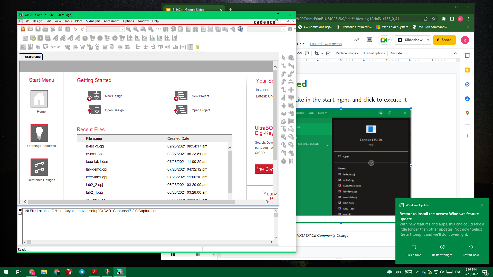
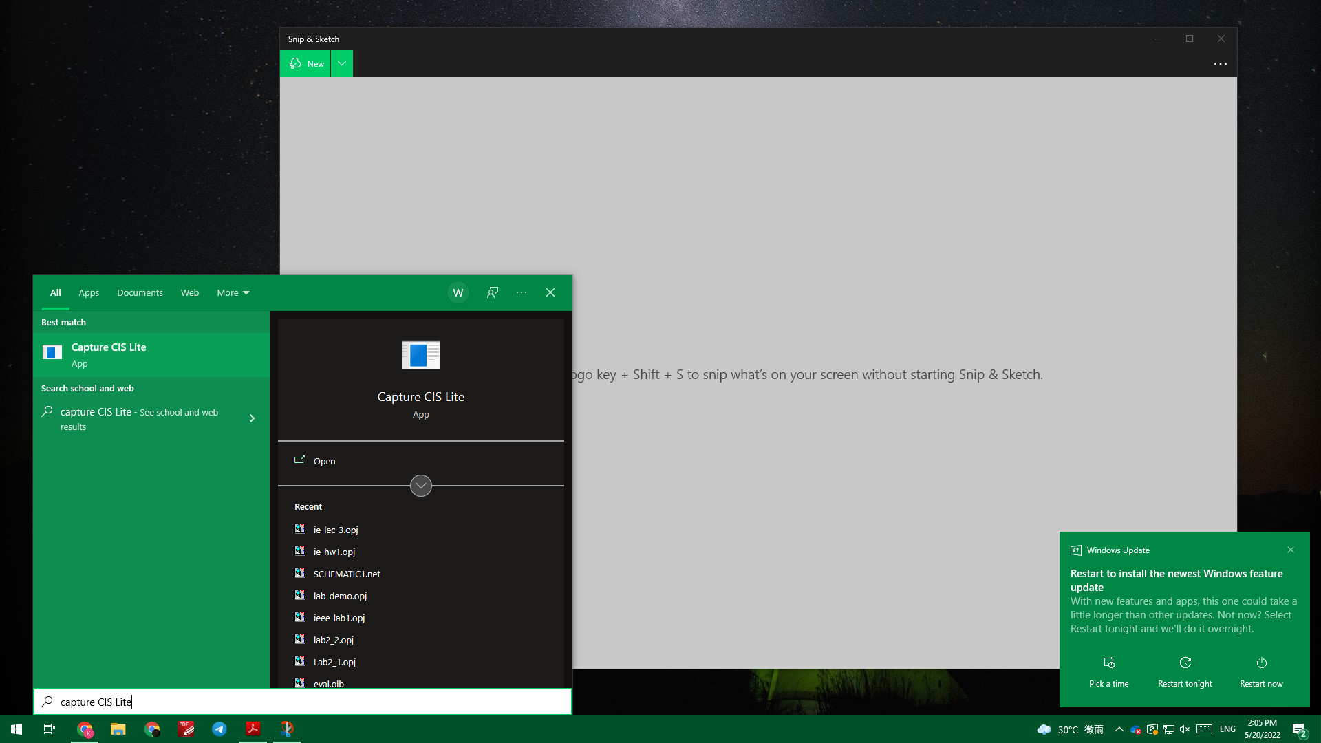
The OrCAD Capture CIS Lite can launched from the Start window. [see Figure 1] Once the software is launched, you will see the programme’s window popping up. [see Figure 2]
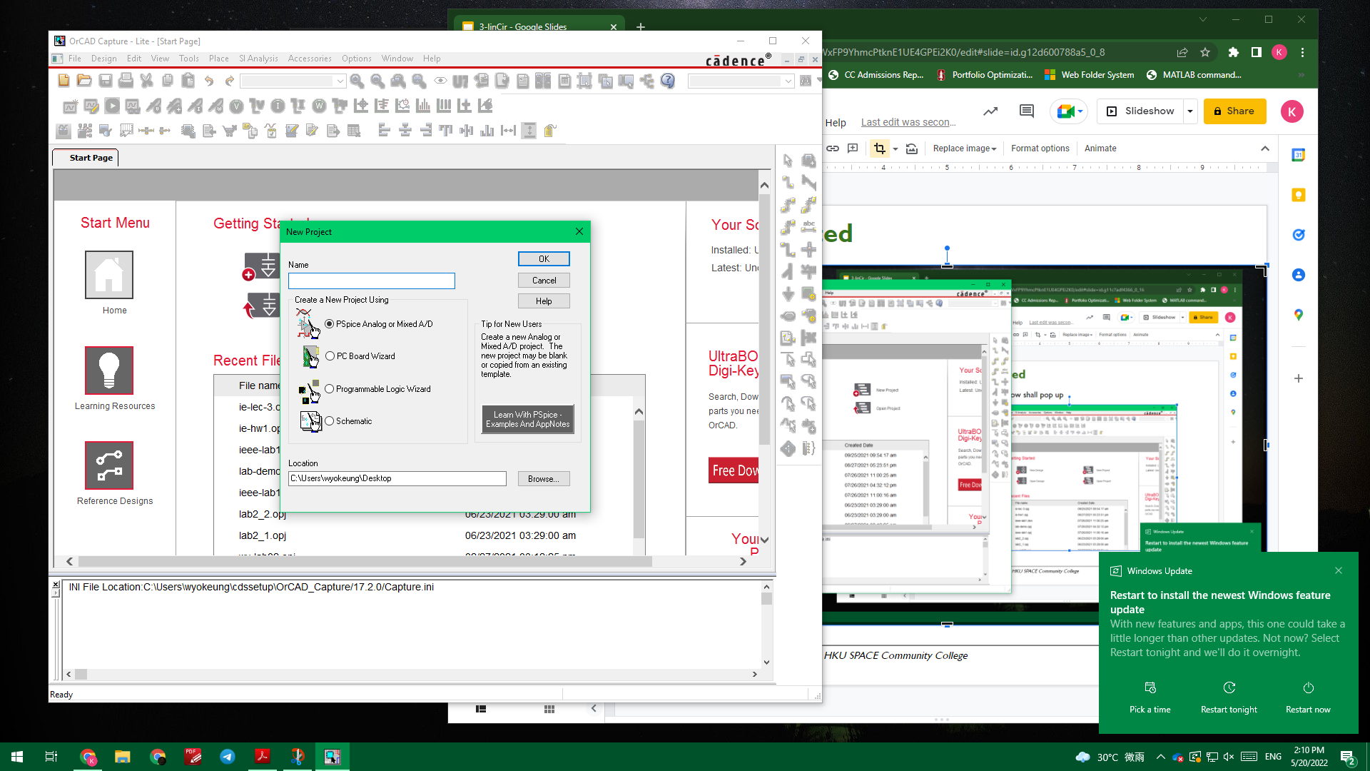
You may start a new project (program) by going to the File menu in the upper left corner, then New, and then Project. The following screen will appear. Be sure that the Analog or Mixed A/D button is activated. [see Figure 3] Change it if necessary. This is VERY important!
Figure 1: Window’s Start Menu
Figure 2: OrCAD Capture Popping up
Figure 3: Opening a New Analog Mixed A/D Project
You will need to fill in the top line Name with a file name and then the bottom line Location with the path name. This is the directory where you will be storing your “Project”. Use the file name ie-lab-2. In all the above fields, do not use any non-English characters, including the project file location you chose. Otherwise, the programme will crash.
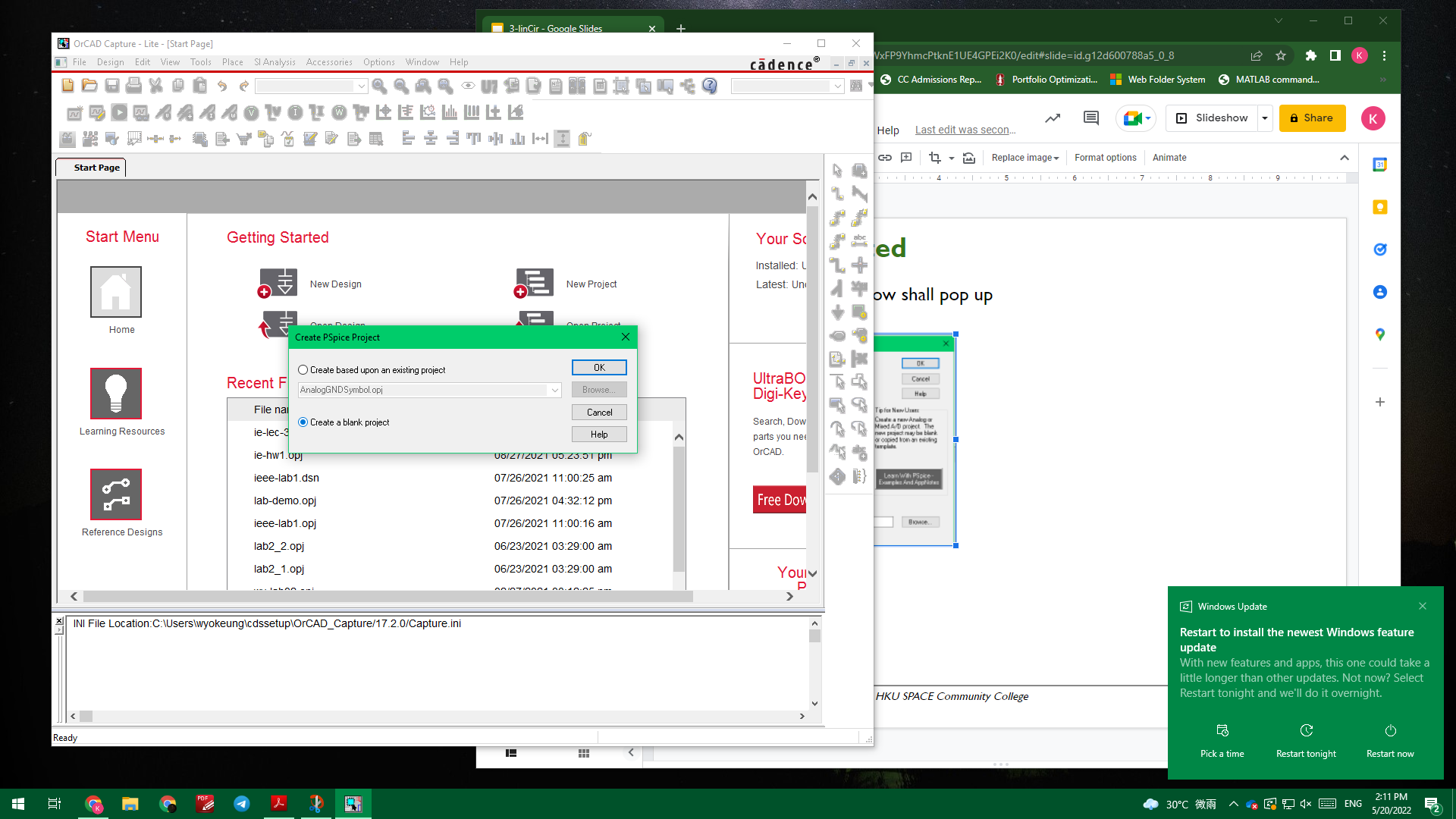
Now the following screen will appear. Since you are starting a new project, change the button settings as shown below. Activate the Create a blank project button and left-click OK.
Figure 4: Creating a New Blank PSpice Project
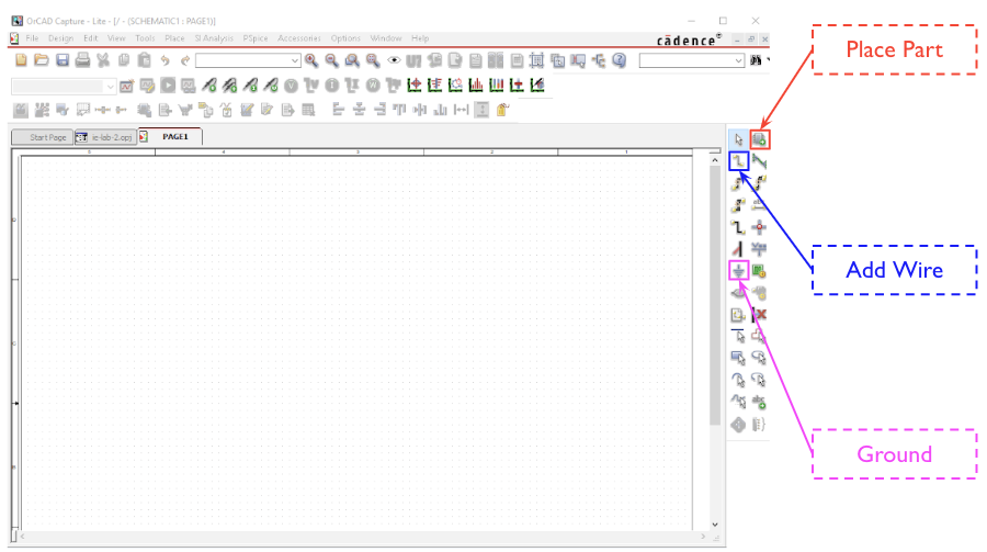
Now you should come up to a blank schematic entry screen.
Figure 5: A Blank Schematic
You can now start adding components and symbols to your schematic, by using the Place Part button in the menu sequence. The three Libraries needed to be loaded are “ANALOG”, “SOURCE” and “EVAL”
At this time, highlight all of the libraries. Then start entering your parts. When you have found the required part, either by entering its name in the Part window or by highlighting its name in the Part List window, left-click OK to place the part onto the schematic. You can continue left-clicking to place multiple copies of the same part or right click to end this selection.
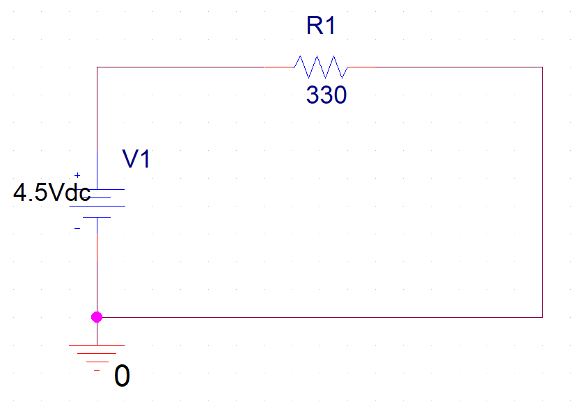
Practice now by entering the schematic shown below. Change the default values and orientations to those shown below.
Figure 6: Demo Circuit
To change a value, or a reference, highlight the appropriate value (left-click) and then double left-clicking. When you have added the resistor (R), and the power supply (VDC) symbols, enter the ground symbol labeled “0”. To place the ground, click Place->Ground. Recall that every circuit has to have a node “0”. Left-click Apply and close the page.
Use the Place, Wire menu sequence or the icon on the right hand side toolbar. Connecting wires requires that you drag the “crosshair” over the end of the part and left-click. This “solders” one end of the wire. Drag the wire to another connecting point and left-click again. You have now “soldered” the other end. You are now ready to stimulate your circuit.
4 PSpice Simulation
4.1 Lighting Up an LED Bulb
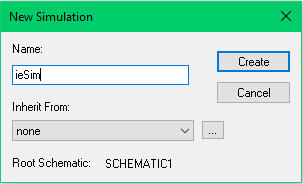
To start the simulation process, open the PSpice menu. The first choice available is New Simulation Profile. Left-click on it and the following window will appear.
Figure 7: Demo Circuit
Give the New Simulation a Name. For now use “Voltage Result”. Left-click Create and the next screen will appear:
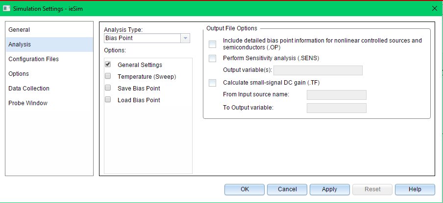
Figure 8: Simulation Settings
For a DC analysis, select the Bias Point setting in the Analysis type: window. Since we do not need that process in this part of our example, go to the Probe Window tab, uncheck the box next to the Display Probe Window setting and then left-click OK. Now you are ready to run a simulation.
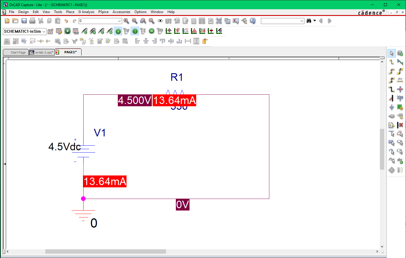
Go to the PSpice tab and select Run. The simulation window will appear. When the simulation has completed, close this window and the schematic will reappear. When the V, I, and W tool buttons are activated, the results of the voltage, the current, and the power dissipated in that component will be shown. The tool buttons alongside the V, I, and W buttons allow you to alternately toggle a highlighted value OFF and ON.
Figure 9: Expected Outcome of the Demo Simulation
Copyright © by W.-Y. Keung 2022